ALEPH-1 Mission and Payload Description Summary

Primary mission demonstration objective

To establish whether ‘micro-habitat’ conditions deemed necessary for the survival of selected "biological components" can be maintained, measured and the necessary data acquired over the mission duration - including 72 hours on the lunar surface.

Funding

Lunaria One Pty Ltd, Australian Space Agency Moon-to-Mars Initiative Demonstrator Award (2022).

Delivery spacecraft

Intuitive Machines, Nova-C lunar lander (IM-3 mission, scheduled for H2 2026).

Interface constraints

  • Mounted to side panel of the Nova-C Spacecraft
  • Payload Mass: ~ 500 grams
  • Heater Power: 10 Watts
  • Avionics Power: 5 Watts
  • Ethernet Interface
  • Data limit 100 Mb

Payload Development and Integration

RMIT M2MIST Centre  

Payload configuration

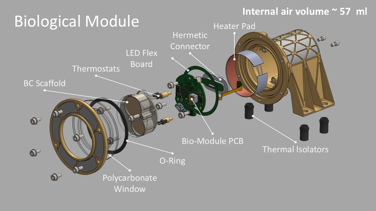
ALEPH-1 (Fig. 1) comprises of a “Control Module” (CM) linked by an umbilical harness to the hermetically sealed “Biological Module” (BM) housing biological components and sensors to measure internal air temperature and pressure (Fig. 2). It is intended that the mission data generated will be transmitted by from the CM to the Nova-C and then downloaded via the Deep Space Network. Data upload capability is also planned. 

Figure 1 ALEPH-1 Architecture

A system architecture diagram titled "Figure 1" showing the ALEPH-1 mission segments. The diagram is divided into a red "Ground Segment" on the left and a green "Space Segment" on the right.

Figure 2 ALEPH-1 BM

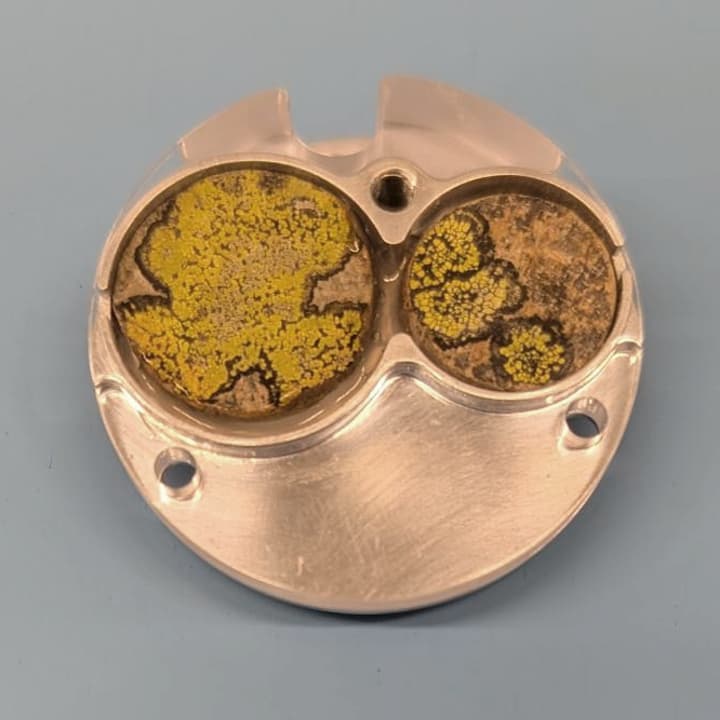
 Biological components (Fig. 3) intended to be carried on BM scaffold: two samples of crustose Map lichen (Rhizocarpon geographicum), selected for resilience to expected pre-flight storage conditions as well as the in-flight and lunar environments.

Figure 3 ALEPH-1 Bio-Scaffold (test version)

 Close-up photograph of a test item of the ALEPH-1 Biological Module Scaffold comprising two circular cells, each holding a sample "tablets" of the yellow-green lichen Rhizocarpon geographicum growing on a rock substrate. The left chamber shows a more uniformly bright yellow-green thallus with some dark lines, while the right chamber displays a patchier appearance with larger areas of brown-black substrate visible. The alloy housing of the module is visible around the cells, with mounting holes and a small 3 mm cavity intended to hold seeds. The photo is taken against a plain light-blue background

The images below (Fig. 4-6) show some aspects of the electronics assembly processes that were all performed at RMIT University.

Figure 4 Lead forming on FPGA component

Figure 4 shows a close-up, top-down view of a highly precise electronics assembly.  Here is a breakdown of what is visible in the image:  The Fixture and Breadboard  Optical Breadboard: The entire assembly is mounted onto a silver, metallic grid plate (an optical breadboard or fixture plate) featuring a pattern of threaded screw holes.  Clamps: Several black and silver mechanical clamps, held down by hex screws, are securing the component setup firmly in place. Central Element: At the center of the fixture rests a delicate micro-electronic component called an FPGA. It features a tiny, square gold pad in the middle.  Fine Wire Arrays: Radiating out from the central area are arrays of extremely fine, parallel gold wires or traces that bridge across a small gap.  Supporting Wings: These delicate wire arrays are connected to purple, wing-like structural tabs with gold contact points at their tips.

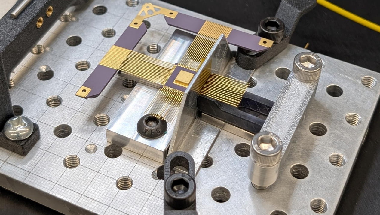
Figure 5 PCBs for the ALEPH-1 CM (engineering model)

Figure 5 shows a detailed, top-down view of a complex electronic assembly consisting of a multi-board printed circuit board (PCB) panel resting on an anti-static surface. Here is a breakdown of what is visible in the image: Board Layout and Structure  Four-Quadrant Design: The main green PCB is a large panel or motherboard divided into four distinct quadrants, each holding a smaller, integrated circuit board module.  Gold-Plated Borders: Each of the four sub-board areas is framed by thick, gold-plated routing lines and features rounded corner tabs with circular mounting holes, similar to the individual boards seen in image.png.  Structural Framing: The entire green board assembly is secured within a gray, precision-machined metal frame or carrier, with copper-colored grounding tabs visible along the bottom edge. Electronic Components Each quadrant contains a unique arrangement of high-density surface-mount components:  Connectors: Long, black, multi-pin board-to-board connectors are mounted on several of the modules.  Integrated Circuits (ICs): There are various black microchips, resistors, capacitors, and small surface-mount devices scattered across the boards.  Specialized Components: Several metallic, gold-colored blocks or shielded packages (potentially sensors or specialized processors) are prominent on three of the four modules.

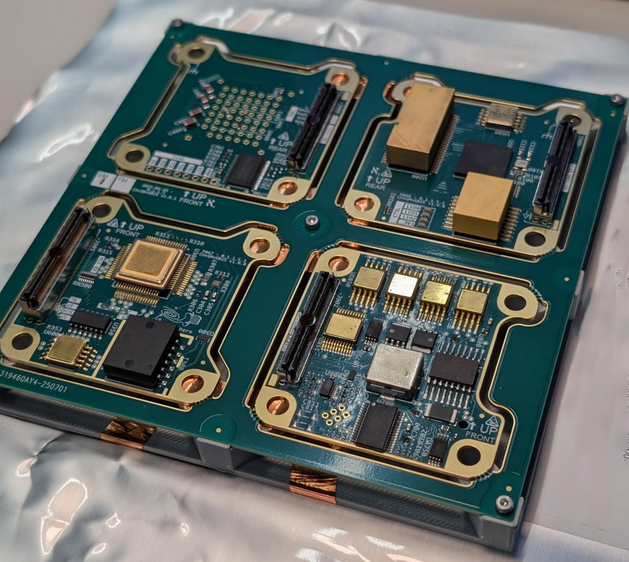
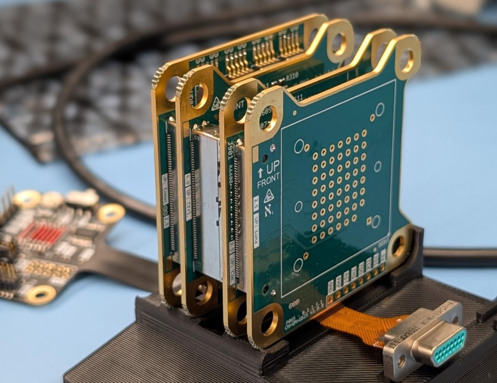
Figure 6 PCB Stack for ALEPH-1 CM (engineering model)

Figure 6  shows a close-up view of a hardware electronics setup on a light blue work surface. Here are the key details visible in the image:  The Main Assembly: In the center, several small, green printed circuit boards (PCBs) with gold-plated edges and mounting holes are stacked vertically next to each other. They are held upright in a black, 3D-printed plastic dock or stand.  Markings and Components: The outermost visible PCB has grid-like pin holes. A ribbon cable extends from the bottom of the board assembly, ending in a metal D-sub connector.  Background Elements: Another smaller, flat circuit board with attached wiring is visible to the left. The background is softly blurred but shows lab or workshop equipment, including what appears to be a computer keyboard, cables, and electronic testing gear.

For more information: on the ALEPH-1, science, mission and payload, please see M2MIST publications, and/or contact graham.dorrington@rmit.edu.au

For more educational outreach aspects of the ALEPH project, please visit https://lunaria.one/aleph/

aboriginal flag float-starttorres strait flag float-start

Acknowledgement of Country

RMIT University acknowledges the people of the Woi wurrung and Boon wurrung language groups of the eastern Kulin Nation on whose unceded lands we conduct the business of the University. RMIT University respectfully acknowledges their Ancestors and Elders, past and present. RMIT also acknowledges the Traditional Custodians and their Ancestors of the lands and waters across Australia where we conduct our business - Artwork 'Sentient' by Hollie Johnson, Gunaikurnai and Monero Ngarigo.

Learn more about our commitment to Indigenous cultures