Neil Wilson
Conformal tooling is an advanced technology used to construct moulds, which are in turn used to mass manufacture plastic parts of complex shapes. Its development continues across the industrialised world due to its promise of producing moulded parts at lower cost. It achieves this by (i) significantly reducing manufacturing cycle time, which is the time required to complete a single moulding cycle from initial polymer injection to extraction of the solidified part from the tool, and (ii) improving the quality of the moulded parts due to closer control of mould cavity temperature uniformity throughout the cycle. Numerous materials may be used for the creation of moulded parts, resulting in a vast array of relevant client industries & products.
The fundamental factors limiting the growth of scale & market penetration of conformal tooling are country-specific, i.e. the presence of advanced manufacturing infrastructure, the availability of skilled multidisciplinary toolmakers capable of incorporating the high-level additive manufacturing (AM) skillset into product development, and simulation capabilities specific to the design of optimised conformal tools. In Australia, the latter is only now becoming established in the form of specific design software components for use with conformal tooling, i.e. heat flux simulation, part deformation, heating/cooling fluid dynamics, all integrated together with mould-filling fluid dynamics. However, these components alone do not deliver a generic methodology for the optimised design of conformal tooling – for this purpose, generative design linkage modules are required that connect the modelling components. Such linkage modules promise conformal tooling design capability that is usable by non-expert users, and these are the focus of my PhD.
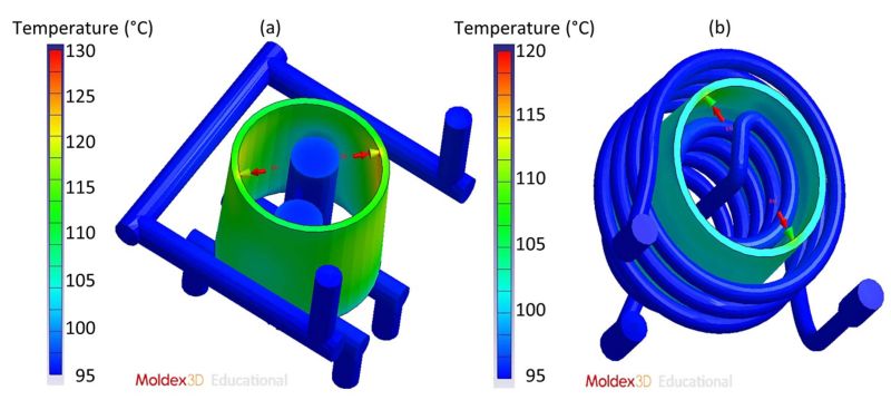
Well-designed conformal tooling demonstrates an optimal (i.e. uniform) temperature distribution (‘heat map’) along the inner surface of the tooling cavity. This is achieved by using additive manufacturing to include channels for heating/cooling fluid to flow near the mould’s cavity-core interface/surface. Predictions of the required number, cross-sectional shape/size, pitch (inter-channel distance & pattern), and clearance between the channels & the cavity surface must be reliably generated to achieve a homogenous heat map in a cost-effective manner, i.e., with the minimum number of built prototypes. These typically multi-objective design calculations are conducted to varying extents by the current stable of process simulation software packages. However, none yet consider the varying heat map at the cavity surface during the final material-filling stage of the injection moulding process. This is now the subject of fierce development by several software houses, including Moldex, Altair, Siemens, and nTopology. My research aims to achieve a manufacturer-neutral (generic) software linkage module of this type, which is furthermore validated against experiments for both single-alloy and bi-metal combinations. We will also examine the effect of the air gap at the cavity surface that develops due to thermal shrinkage of the moulded part during its cooling & solidification cycle.
The project is conducted in conjunction with Romar Engineering Pty Ltd & CSIRO.


Materials Modelling
Computational fluid dynamics (CFD), fluid-structure interaction (FSI), 3D printing (stereolithography, PolyJet), selective laser melting, modelling process, direct laser metal deposition, fused deposition modelling, object printing