Felix Nugraha Lomo
Cold spray (CS) is a solid-state, high-rate material deposition process resulting in metallic 3D structures built at kg/hour (Hussain, 2012). Since its discovery, CS has grown from a coating technology into a near-net shape additive manufacturing (AM) technology. However, much cold spray additive manufacturing (CSAM) research has been limited to geometries with 2D axisymmetric profiles rotated on their axis to produce the manufactured part. There is limited research literature on an overall framework for fabricating complex structural (i.e. load-bearing) parts via CSAM. These limitations include:
- Materials selection for the sprayed powder material
- Toolpath planning for the CSAM robot to spray the part efficiently and to reasonable dimensional tolerances
- Strategies for spraying complex webs and flanges and post-machining
With respect to material selection, the commonest choice for a structural material for aerospace applications is titanium (Ti) and its alloys, particularly Ti-6Al-4V. Whilst it is possible to spray higher strength Ti alloys such as Ti-6Al-4V, these alloys typically have a higher yield strength (are less plastically deformable) and therefore feature a higher critical velocity during deposition before which they will combine into the deposit without excessive voids that negatively affect its mechanical properties. Spraying pure metals is easier than their alloy counterparts for this reason; however, achieving the strength properties required for structural application then becomes nearly impossible.
CSAM of Ti particles combined with hard ceramic particles to form a metal matrix composite (MMC) deposit has been proposed to reduce porosity formation in situ and thus improve the deposit material's mechanical strength. Hard ceramic particles are candidate powder feedstock additives as during the release of their kinetic energy upon impact with the softer Ti matrix, they may more intensively tamp the deposit than the softer Ti particles, thus shrinking the deposit’s voids. The combined effects of porosity reduction and embedding of relatively hard particles thus improve the deposit's strength. In this research, three different hard particle types were mixed with a commercial-purity (CP) Ti feedstock powder (Grade 2) to create four different MMCs. These include (i) yttria-stabilised zirconia – (ZrO2)0.92(Y2O3)0.08, (ii) titanium diboride – TiB2, and (iii) titanium carbide – TiC. A fourth mixture was produced by blending the Ti feedstock with tungsten – W. Post-heat treatment was performed on all four MMCs using a vacuum furnace at 1100°C using an initial ramp rate of 15°C/min, hold time of 2 hours, and fan-assisted cooling. The results from this study showed that the addition of secondary phase material did not improve either the deposition efficiency of the CP Ti matrix or reduce the total pore volume fraction by more intensive tamping. The post-heat treatment described above reduced the total porosity of the deposit (as expected). The blends of CP Ti with TiB2 & W underwent interdiffusion with the Ti matrix to create TiBw and Ti-W phases, respectively. Overall, the combination of second-phase addition and post-heat treatment let to increases of 8 - 27% in tensile yield strength for all four CP Ti MMCs tested.
Aside from the aforementioned limitation of needing to find materials suitable for spraying to produce low-porosity deposits and high strength for structural applications, there is limited literature on Ti CSAM fabrication of parts with complex 3D geometries, e.g. thin vertical walls. This is likely because low-porosity Ti deposits are more difficult to produce than for, e.g. Cu & Al (Wu et al., 2020). Resolving this research gap would permit the building of more intricate 3D Ti parts and thus the industrialisation of Ti CSAM processing. In this project, producing a real structural component that includes such features is therefore considered a sound strategy to deliver a credible benchmark & milestone for Ti CSAM manufacturing technology. The 'GE Jet Engine Bracket' GrabCAD challenge was published in June 2013 and provides such a robust benchmark. Design optimisation & CS process parameter identification are currently underway.
This project is conducted in conjunction with CSIRO.
Publications
- FN Lomo, A Vargas-Uscategui, PC King, MJ Patel, IS Cole (2023). ‘Microstructure and mechanical properties of heat-treated cold spray additively manufactured titanium metal matrix composites’, Journal of Manufacturing Processes, 99, 12-26.
- FN Lomo, MJ Patel, A Vargas-Uscategui, PC King, IS Cole (2023). ‘A design & optimisation framework for cold spray additive manufacturing of lightweight aerospace structural components’ [UNDER PREPARATION].
![Schematic of a typical cold spray additive manufacturing system. A 6-axis industrial robot arm is used to either hold the spray gun or the workpiece [2]](/assets/rmit-images/research/institutes-centres-and-groups/RDF/felix-fig1.png) Figure 1: Schematic of a typical cold spray additive manufacturing system. A 6-axis industrial robot arm is used to either hold the spray gun or the workpiece [2]
Figure 1: Schematic of a typical cold spray additive manufacturing system. A 6-axis industrial robot arm is used to either hold the spray gun or the workpiece [2]
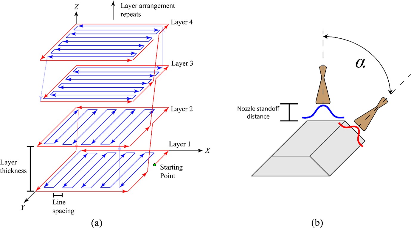 Figure 2: (a) The double cross-hatching toolpath plan was utilised in this study (Lomo et al., 2023). The blue line indicates the infill pass, and the red line indicates the contour pass. (b) The nozzle will be perpendicular to the deposit when performing the infill pass and then tilted to an angle (α) to perform the contour pass. This tilting motion will allow the deposit to be built with vertical walls, i.e. without experiencing any edge loss due to the (usually) tapering nature of a CSAM deposition.
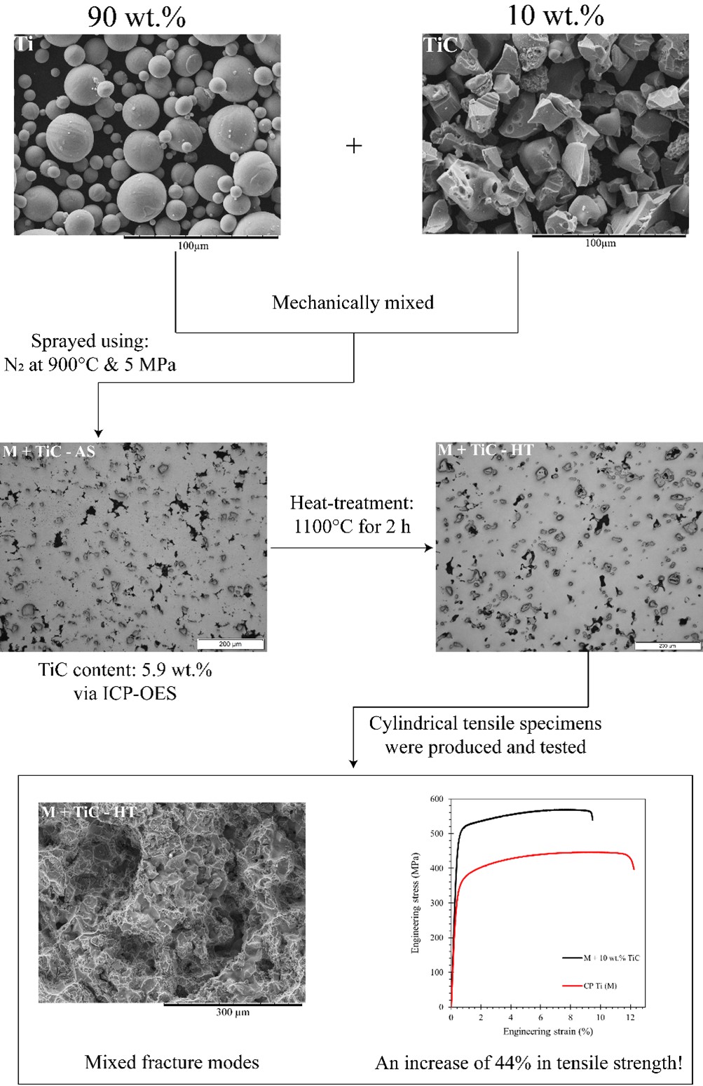 Figure 3: Workflow to mix, spray, and test a Ti + 10 wt.% TiC metal matrix composite (MMC) deposit
![Schematic of a typical cold spray additive manufacturing system. A 6-axis industrial robot arm is used to either hold the spray gun or the workpiece [2]](/assets/rmit-images/research/institutes-centres-and-groups/RDF/felix-fig2a.png) Figure 2: (a) Original GE Jet Engine Bracket Challenge design, which contains 2.084 kg of metal; this design is taken from the associated GrabCAD Challenge from 2013
Figure 2: (a) Original GE Jet Engine Bracket Challenge design, which contains 2.084 kg of metal; this design is taken from the associated GrabCAD Challenge from 2013
![Schematic of a typical cold spray additive manufacturing system. A 6-axis industrial robot arm is used to either hold the spray gun or the workpiece [2]](/assets/rmit-images/research/institutes-centres-and-groups/RDF/felix-fig2b.png) (b) a CSAM-optimised design produced during this research that requires just 780 g of metal.
(b) a CSAM-optimised design produced during this research that requires just 780 g of metal.
Figure 4: (a) Original GE Jet Engine Bracket Challenge (2013), which contains 2084 g of metal for the challenge’s baseline (unoptimised) design, and (b) a weight-optimised design intended for CSAM production developed during this research that requires just 780 g of metal.
 (a)
(a)
 (b)
(b)
 (c)
(c)
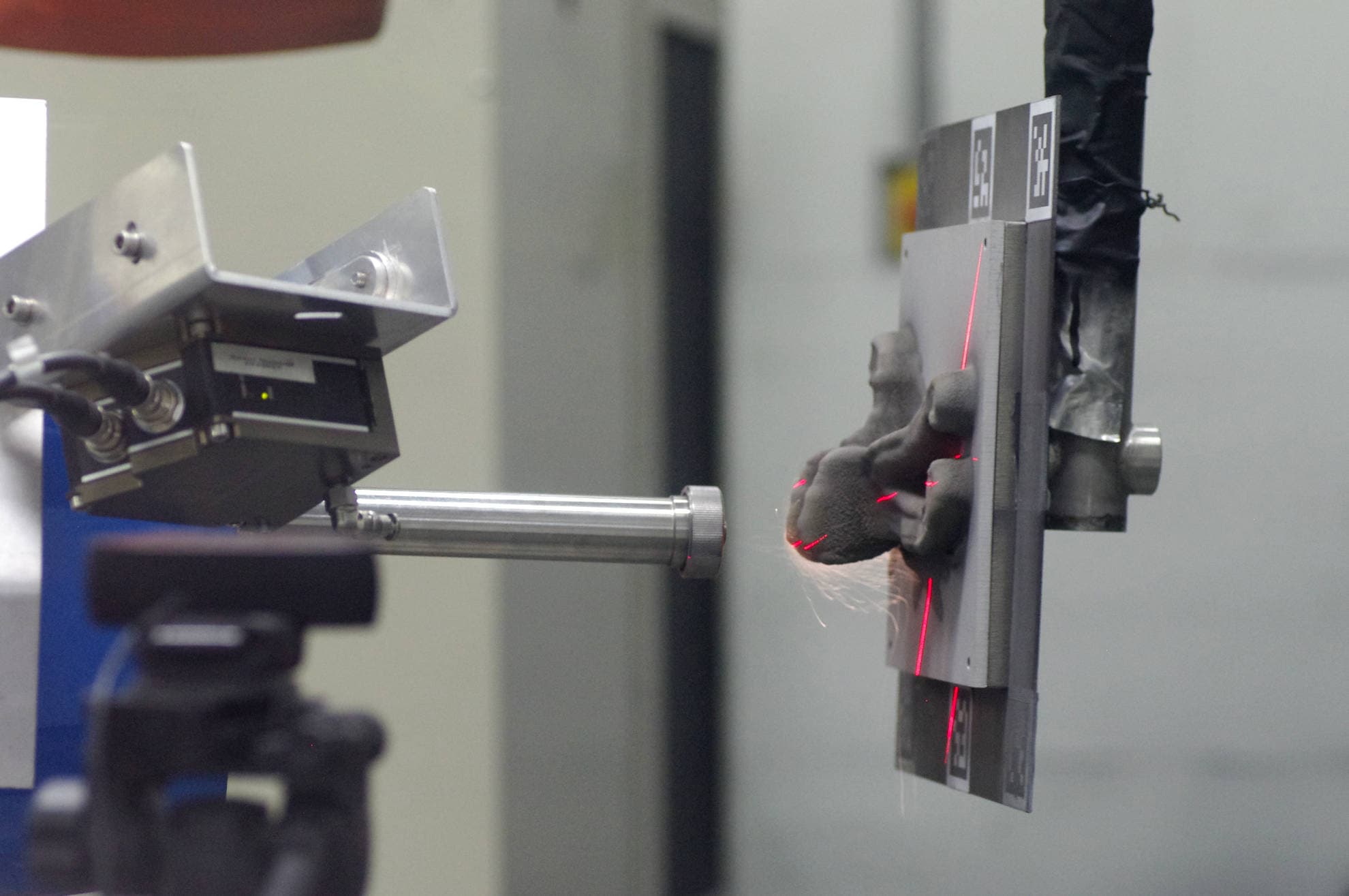
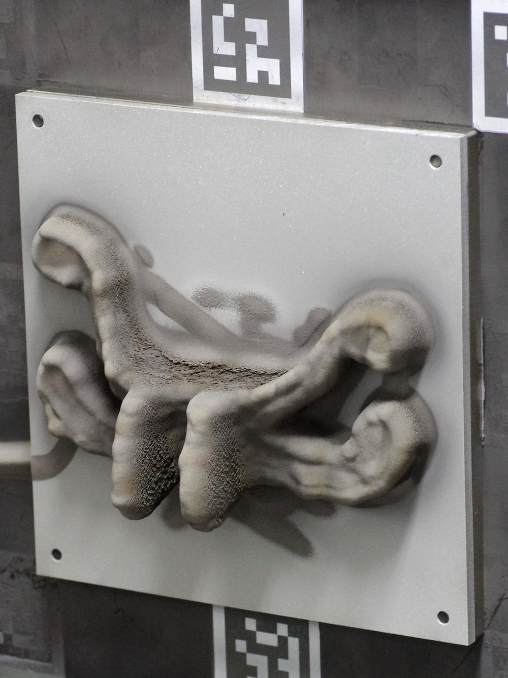
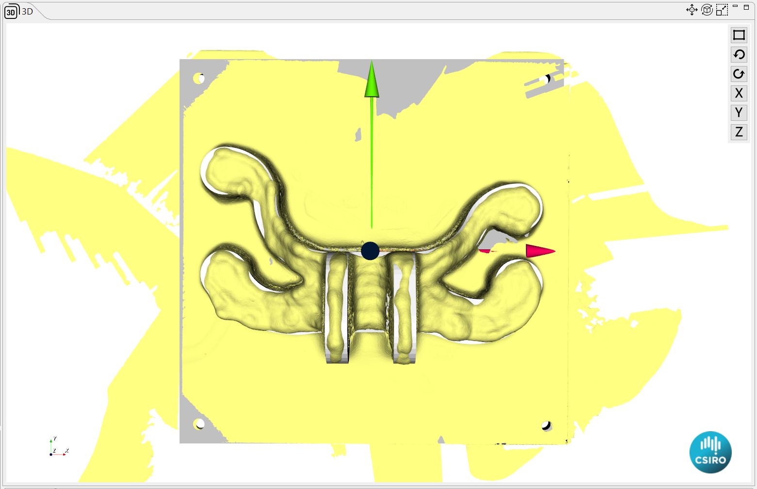
Figure 5: GE jet engine bracket design developed here that is optimised for CSAM production and requires just 780 g of metal instead of the 2084 g required by the challenge’s baseline (unoptimised) design. (a) Photo taken during CSAM of the optimised 'octopus’-shaped design, and (b) photo of finished engine bracket prior to heat treatment; loose Ti is visible, particularly on the overhanging sections. (c) 3D scan of the as-sprayed part (yellow) obtained using a LiDAR scanner with the original 3D CAD model (white) superimposed. Further analysis will be performed to quantify the differences between these geometries to determine areas where the build parameters need local adjustment.
References
[1] T. Hussain (2012). 'Cold spraying of titanium: a review of bonding mechanisms, microstructure and properties," Key Engineering Materials, vol. 533, pp. 53–90, DOI: 10.4028/www.scientific.net/kem.533.53.
[2] H Wu, X Xie, M Liu, C Verdy, Y Zhang, H Liao & S Deng. (2020). 'Stable layer-building strategy to enhance cold-spray-based additive manufacturing', Additive Manufacturing, vol. 35, 101356, DOI: 10.1016/j.addma.2020.101356.
[3] A. Vargas-Uscategui, P. C. King, S. Yang, C. Chu, and J. Li, “Toolpath planning for cold spray additively manufactured titanium walls and corners: Effect on geometry and porosity,” J. Mater. Process. Technol., vol. 298, p. 117272, 2021, doi: https://doi.org/10.1016/j.jmatprotec.2021.117272.
Metal Fabrication
Cold spray, melt pool, friction stir welding, multifunctional coatings for biomedical Mg alloys, visual monitoring of metal powder